Optimize Air Chain
Overshoot Source
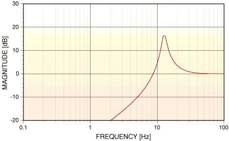
Extensive computer modeling and analysis of several current-generation composite STL systems and FM exciters has revealed that the overshoot problem is not in the high frequency domain (as previously assumed), but instead at infrasonic frequencies. All of the systems modeled have infrasonic peaks in their frequency response, and/or have insufficient low-frequency response to accurately reproduce a processed composite baseband signal. Some of the systems even suffer from marked non-linearity, having different frequency response at different modulation levels at very low frequencies, aggravating the problem. This poor low-frequency transient response can be caused by incorrectly designed AFC loops and/or deficient low-frequency response of the composite baseband amplifiers. Figs. 6, 7, and 8 show the system response of three popular composite STL systems. Figs. 9, 10, and 11 show the system response of three popular FM exciters. Note the radical differences in low-frequency response, and how the response of a given system depends on its RF operating frequency. It's no surprise or myth that each of these modulators has its own sonic signature as well. (This might explain why legend has it that certain FM channels sound better than others!) Note also that of the systems modeled here, the newer systems do not have better performance. Contrary to popular belief, science does not always march forward!

Fig. 6 STL SYSTEM 1 INFRASONIC FREQUENCY RESPONSE
Moseley Associates, Inc. PCL-606/C

Fig. 7 STL SYSTEM 2 INFRASONIC FREQUENCY RESPONSE
Moseley Associates, Inc. PCL-6010/C

Fig. 8a STL SYSTEM 3 INFRASONIC FREQUENCY RESPONSE
TFT, Inc. 8300 - Original Design

Fig. 8b STL SYSTEM 3 INFRASONIC FREQUENCY RESPONSE
TFT, Inc. 8300 - Updated Design

Fig. 9 FM EXCITER 1 INFRASONIC FREQUENCY RESPONSE
Broadcast Electronics, Inc. FX-50

Fig. 10 FM EXCITER 2 INFRASONIC FREQUENCY RESPONSE
Continental Electronics Mfg., Co., Inc. 802A

Fig. 11 FM EXCITER 3 INFRASONIC FREQUENCY RESPONSE
Continental Electronics Mfg., Co., Inc. 802B
Another important consideration is the overall system performance of the various components in the composite signal path. When these components are cascaded, the system response deteriorates. The amount of degradation depends on input and output impedance interactions in the composite baseband amplifiers and how many systems are cascaded, so the audible performance of a system is not always simply the sum of the performance of its parts. Fig. 12 shows the total system response of STL 2 and Exciter 3. Note how the response has further degraded. (Once again, this might explain why legend contends that certain combinations of equipment sound better than others.)

Fig. 12 STL SYSTEM 2 AND EXCITER 3 TOTAL SYSTEM RESPONSE
Peak-Weighted Monitoring
Recently, on the basis of a controversial interpretation of the FCC Rules & Regulations, devices have been introduced that change the way that broadcasters measure modulation. By delaying the response of the peak indicator, such a modulation monitor ignores peaks of less than 1 millisecond duration (assumed to be overshoots), and does not indicate over-modulation under these conditions. Although this technique of modulation measurement is under close investigation by the industry (for reasons not relevant here), it does not ignore the type of composite baseband overshoot described above. Instead, provided the peak indicator circuitry has been designed correctly, the modulation monitor accurately measures this overshoot because its duration is far longer than the delay of the peak indicator. So the composite path must still be free from infrasonic overshoot to preserve peak control providing maximum loudness with minimum distortion. Fig. 13 shows STL system 2 peak modulation, peak- weighted with 9 cycles at 10kHz. Note there is little difference between Fig. 13 and Fig. 2, which once again, is the exact same program material and segment.

Fig. 13 STL SYSTEM 2 PEAK MODULATION
Peak Weighted, 9 cycles/10kHz
Response Requirements
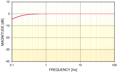
If we model the system (to a first-order approximation), as a high-pass filter with a single dominant pole, we can use the equation in Fig. 14 to compute the percentage of overshoot when a square-wave of frequency F (Hz) is applied to the system input. This overshoot will occur regardless of whether the low-frequency rolloff is in the composite channel, or in the left and right audio channels after peak limiting. In the former case, the rolloff can also compromise low-frequency separation. To achieve less than 1% overshoot with a 50Hz square-wave (a reasonable criterion for good peak control), the dominant pole must be located at 0.16Hz or lower with no peaking! Good 10Hz square-wave response does not predict low overshoot because a peak in the region below 10Hz can phase equalize the 10Hz fundamental while simultaneously distorting the phase and amplitude of the components below 10Hz. If more than one low-frequency roll-off element is cascaded in the composite path, each element's cut-off frequency must be substantially below 0.16Hz. Fig. 15 shows the minimum required low-frequency response.

Fig. 14 OVERSHOOT EXPRESSION

Fig. 15 MINIMUM LOW-FREQUENCY RESPONSE REQUIREMENT
Linear Solution
Since poor infrasonic frequency response causes composite baseband overshoot, it can be eliminated by the proper design of the AFC circuitry and composite baseband amplifiers. It can also be corrected (although not as accurately) by an infrasonic equalizer that flattens the very low-frequency response of the composite signal path. Both methods are linear solutions to linear problems. The first method is preferred. Unlike composite baseband clippers, linear correction produces no distortion or aliasing products, ensuring maximum loudness without side-effects.
Highly optimized modifications to most current generation FM exciters and STL systems permit these units to pass the most highly-processed composite baseband signal while adding less than 1% overshoot - often an improvement of 10:1 or more, resulting in a 1dB loudness advantage with almost any audio processing. This can be a very cost-effective solution, offering better sonic performance than digital alternatives because there is no data compression to potentially cause distortion. These modifications offer better performance than all of the latest unmodified analog equipment known to us. Fig. 16 shows the optimized response of the STL System 2, shown in Fig. 7. Fig. 17 shows the optimized response of the FM Exciter 2, shown in Fig. 10. Figs. 18 and 19 show the results of the optimization of STL System 2 and FM Exciter 2 respectively by indicating tight peak modulation control. Note the before optimization peak control in Figs. 2 and 3.

Fig. 16 STL SYSTEM 2 OPTIMIZED RESPONSE
Moseley Associates, Inc. PCL-6010/C

Fig. 17 FM EXCITER 2 OPTIMIZED RESPONSE
Continental Electronics Mfg., Co., Inc. 802B

Fig. 18 STL SYSTEM 2 PEAK MODULATION-After Modification
Moseley Associates, Inc. PCL-6010/C

Fig. 19 FM EXCITER 2 PEAK MODULATION-After Modification
Continental Electronics Mfg., Co., Inc. 802B
Getting a signal as loud as possible under existing government regulations requires attention to every link in the audio chain. One or more weak links can noticeably decrease the loudness and competitiveness of the signal. In broadcast audio, as in most other endeavors, attention to detail separates the winners from the losers.
Greg J. Ogonowski
MODULATION INDEX Diamond Bar, California USA
TEL (909) 860-6760 FAX (909) 860-6829
Portions Reprinted from 1990 NAB ENGINEERING CONFERENCE PROCEEDINGS
Portions Reprinted from 1993 NAB ENGINEERING HANDBOOK
Portions COPYRIGHT 1990, 1993 NAB Washington, DC USA
Portions COPYRIGHT 1993, 1995, 1996 MODULATION INDEX Diamond Bar, CA USA
To return click here: Optimize Air Chain 1, or Optimize Air Chain 2
